Data-link layer uses error control techniques to ensure that frames, i.e. bit streams of data, are transmitted from the source to the destination with a certain extent of accuracy.
Errors
When bits are transmitted over the computer network, they are subject to get corrupted due to interference and network problems. The corrupted bits leads to spurious data being received by the destination and are called errors.
Types of Errors
Errors can be of three types, namely single bit errors, multiple bit errors, and burst errors.
Single bit error − In the received frame, only one bit has been corrupted, i.e. either changed from 0 to 1 or from 1 to 0.
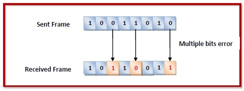
Multiple bits error − In the received frame, more than one bits are corrupted.
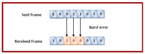
Burst error − In the received frame, more than one consecutive bits are corrupted.
Error Control
Error control can be done in two ways
Error detection − Error detection involves checking whether any error has occurred or not. The number of error bits and the type of error does not matter.
Error correction − Error correction involves ascertaining the exact number of bits that has been corrupted and the location of the corrupted bits.
For both error detection and error correction, the sender needs to send some additional bits along with the data bits. The receiver performs necessary checks based upon the additional redundant bits. If it finds that the data is free from errors, it removes the redundant bits before passing the message to the upper layers.
Error Detection Techniques
There are three main techniques for detecting errors in frames: Parity Check, Checksum and Cyclic Redundancy Check (CRC).
Parity Check
The parity check is done by adding an extra bit, called parity bit to the data to make a number of 1s either even in case of even parity or odd in case of odd parity.
While creating a frame, the sender counts the number of 1s in it and adds the parity bit in the following way
In case of even parity: If a number of 1s is even then parity bit value is 0. If the number of 1s is odd then parity bit value is 1.
In case of odd parity: If a number of 1s is odd then parity bit value is 0. If a number of 1s is even then parity bit value is 1.
On receiving a frame, the receiver counts the number of 1s in it. In case of even parity check, if the count of 1s is even, the frame is accepted, otherwise, it is rejected. A similar rule is adopted for odd parity check.
The parity check is suitable for single bit error detection only.
Checksum
In this error detection scheme, the following procedure is applied
Data is divided into fixed sized frames or segments.
The sender adds the segments using 1’s complement arithmetic to get the sum. It then complements the sum to get the checksum and sends it along with the data frames.
The receiver adds the incoming segments along with the checksum using 1’s complement arithmetic to get the sum and then complements it.
If the result is zero, the received frames are accepted; otherwise, they are discarded.
Cyclic Redundancy Check (CRC)
Cyclic Redundancy Check (CRC) involves binary division of the data bits being sent by a predetermined divisor agreed upon by the communicating system. The divisor is generated using polynomials.
Here, the sender performs binary division of the data segment by the divisor. It then appends the remainder called CRC bits to the end of the data segment. This makes the resulting data unit exactly divisible by the divisor.
The receiver divides the incoming data unit by the divisor. If there is no remainder, the data unit is assumed to be correct and is accepted. Otherwise, it is understood that the data is corrupted and is therefore rejected.
Error Correction Techniques
Error correction techniques find out the exact number of bits that have been corrupted and as well as their locations. There are two principle ways
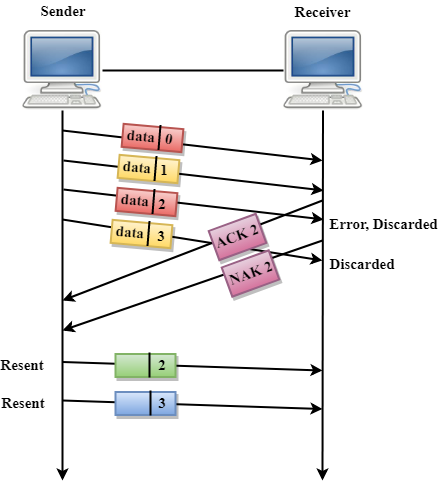
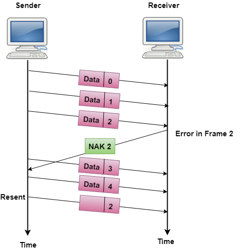
Backward Error Correction (Retransmission) − If the receiver detects an error in the incoming frame, it requests the sender to retransmit the frame. It is a relatively simple technique. But it can be efficiently used only where retransmitting is not expensive as in fiber optics and the time for retransmission is low relative to the requirements of the application.
Forward Error Correction − If the receiver detects some error in the incoming frame, it executes error-correcting code that generates the actual frame. This saves bandwidth required for retransmission. It is inevitable in real-time systems. However, if there are too many errors, the frames need to be retransmitted.
The four main error correction codes are
- Hamming Codes
- Binary Convolution Code
- Reed – Solomon Code
- Low-Density Parity-Check Code

