Example:
Error Correction
Error Correction codes are used to detect and correct the errors when data is transmitted from the sender to the receiver.
Error Correction can be handled in two ways:
- Backward error correction: Once the error is discovered, the receiver requests the sender to retransmit the entire data unit.
- Forward error correction: In this case, the receiver uses the error-correcting code which automatically corrects the errors.
A single additional bit can detect the error, but cannot correct it.
For correcting the errors, one has to know the exact position of the error. For example, If we want to calculate a single-bit error, the error correction code will determine which one of seven bits is in error. To achieve this, we have to add some additional redundant bits.
Suppose r is the number of redundant bits and d is the total number of the data bits. The number of redundant bits r can be calculated by using the formula:
2r>=d+r+1
The value of r is calculated by using the above formula. For example, if the value of d is 4, then the possible smallest value that satisfies the above relation would be 3.
To determine the position of the bit which is in error, a technique developed by R.W Hamming is Hamming code which can be applied to any length of the data unit and uses the relationship between data units and redundant units.
Hamming Code
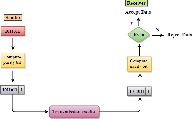
Parity bits: The bit which is appended to the original data of binary bits so that the total number of 1s is even or odd.
Even parity: To check for even parity, if the total number of 1s is even, then the value of the parity bit is 0. If the total number of 1s occurrences is odd, then the value of the parity bit is 1.
Odd Parity: To check for odd parity, if the total number of 1s is even, then the value of parity bit is 1. If the total number of 1s is odd, then the value of parity bit is 0.
Algorithm of Hamming code:
- An information of 'd' bits are added to the redundant bits 'r' to form d+r.
- The location of each of the (d+r) digits is assigned a decimal value.
- The 'r' bits are placed in the positions 1,2,.....2k-1.
- At the receiving end, the parity bits are recalculated. The decimal value of the parity bits determines the position of an error.
--------------------------------------- --------------------------------------- ------------------
Let's understand the concept of Hamming code through an example:
Suppose the original data is 1010 which is to be sent.
Total number of data bits 'd' = 4
Number of redundant bits r : 2r >= d+r+1
2r>= 4+r+1
Therefore, the value of r is 3 that satisfies the above relation.
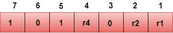
Total number of bits = d+r = 4+3 = 7;
Determining the position of the redundant bits
The number of redundant bits is 3. The three bits are represented by r1, r2, r4. The position of the redundant bits is calculated with corresponds to the raised power of 2. Therefore, their corresponding positions are 1, 21, 22.
Representation of Data on the addition of parity bits:
Determining the Parity bits
Determining the r1 bit
The r1 bit is calculated by performing a parity check on the bit positions whose binary representation includes 1 in the first position.
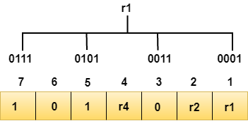
We observe from the above figure that the bit positions that includes 1 in the first position are 1, 3, 5, 7. Now, we perform the even-parity check at these bit positions. The total number of 1 at these bit positions corresponding to r1 is even, therefore, the value of the r1 bit is 0.
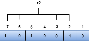
Determining r2 bit
The r2 bit is calculated by performing a parity check on the bit positions whose binary representation includes 1 in the second position.
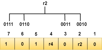
We observe from the above figure that the bit positions that includes 1 in the second position are 2, 3, 6, 7. Now, we perform the even-parity check at these bit positions. The total number of 1 at these bit positions corresponding to r2 is odd, therefore, the value of the r2 bit is 1.
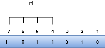
Determining r4 bit
The r4 bit is calculated by performing a parity check on the bit positions whose binary representation includes 1 in the third position.
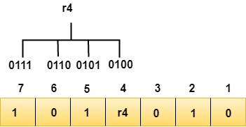
We observe from the above figure that the bit positions that includes 1 in the third position are 4, 5, 6, 7. Now, we perform the even-parity check at these bit positions. The total number of 1 at these bit positions corresponding to r4 is even, therefore, the value of the r4 bit is 0.
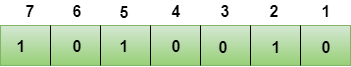
Data transferred is given below:
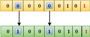
Suppose the 4th bit is changed from 0 to 1 at the receiving end, then parity bits are recalculated.
R1 bit
The bit positions of the r1 bit are 1,3,5,7
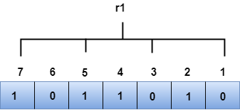
We observe from the above figure that the binary representation of r1 is 1100. Now, we perform the even-parity check, the total number of 1s appearing in the r1 bit is an even number. Therefore, the value of r1 is 0.
R2 bit
The bit positions of r2 bit are 2,3,6,7.
We observe from the above figure that the binary representation of r2 is 1001. Now, we perform the even-parity check, the total number of 1s appearing in the r2 bit is an even number. Therefore, the value of r2 is 0.
R4 bit
The bit positions of r4 bit are 4,5,6,7.
We observe from the above figure that the binary representation of r4 is 1011. Now, we perform the even-parity check, the total number of 1s appearing in the r4 bit is an odd number. Therefore, the value of r4 is 1.
- The binary representation of redundant bits, i.e., r4r2r1 is 100, and its corresponding decimal value is 4. Therefore, the error occurs in a 4th bit position. The bit value must be changed from 1 to 0 to correct the error.
--------------------------- ------------------------------ ------------------------- ---------
Hamming code is a set of error-correction codes that can be used to detect and correct the errors that can occur when the data is moved or stored from the sender to the receiver. It is technique developed by R.W. Hamming for error correction.
Redundant bits –
Redundant bits are extra binary bits that are generated and added to the information-carrying bits of data transfer to ensure that no bits were lost during the data transfer.
The number of redundant bits can be calculated using the following formula:
The number of redundant bits can be calculated using the following formula:
2^r ≥ m + r + 1
 where, r = redundant bit, m = data bit
Suppose the number of data bits is 7, then the number of redundant bits can be calculated using:
= 2^4 ≥ 7 + 4 + 1
Thus, the number of redundant bits= 4
= 2^4 ≥ 7 + 4 + 1
Thus, the number of redundant bits= 4
Parity bits –
A parity bit is a bit appended to a data of binary bits to ensure that the total number of 1’s in the data is even or odd. Parity bits are used for error detection. There are two types of parity bits:
A parity bit is a bit appended to a data of binary bits to ensure that the total number of 1’s in the data is even or odd. Parity bits are used for error detection. There are two types of parity bits:
- Even parity bit:
In the case of even parity, for a given set of bits, the number of 1’s are counted. If that count is odd, the parity bit value is set to 1, making the total count of occurrences of 1’s an even number. If the total number of 1’s in a given set of bits is already even, the parity bit’s value is 0. - Odd Parity bit –
In the case of odd parity, for a given set of bits, the number of 1’s are counted. If that count is even, the parity bit value is set to 1, making the total count of occurrences of 1’s an odd number. If the total number of 1’s in a given set of bits is already odd, the parity bit’s value is 0.
General Algorithm of Hamming code –
The Hamming Code is simply the use of extra parity bits to allow the identification of an error.
The Hamming Code is simply the use of extra parity bits to allow the identification of an error.
- Write the bit positions starting from 1 in binary form (1, 10, 11, 100, etc).
- All the bit positions that are a power of 2 are marked as parity bits (1, 2, 4, 8, etc).
- All the other bit positions are marked as data bits.
- Each data bit is included in a unique set of parity bits, as determined its bit position in binary form.
a. Parity bit 1 covers all the bits positions whose binary representation includes a 1 in the least significant
position (1, 3, 5, 7, 9, 11, etc).
b. Parity bit 2 covers all the bits positions whose binary representation includes a 1 in the second position from
the least significant bit (2, 3, 6, 7, 10, 11, etc).
c. Parity bit 4 covers all the bits positions whose binary representation includes a 1 in the third position from
the least significant bit (4–7, 12–15, 20–23, etc).
d. Parity bit 8 covers all the bits positions whose binary representation includes a 1 in the fourth position from
the least significant bit bits (8–15, 24–31, 40–47, etc).
e. In general, each parity bit covers all bits where the bitwise AND of the parity position and the bit position is
non-zero. - Since we check for even parity set a parity bit to 1 if the total number of ones in the positions it checks is
odd. - Set a parity bit to 0 if the total number of ones in the positions it checks is even.
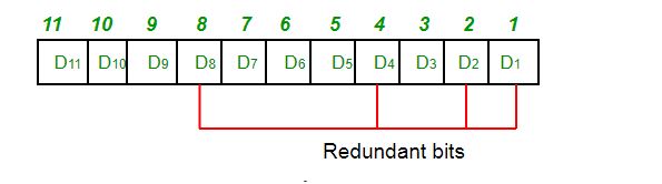
Determining the position of redundant bits –
These redundancy bits are placed at the positions which correspond to the power of 2.
As in the above example:
These redundancy bits are placed at the positions which correspond to the power of 2.
As in the above example:
- The number of data bits = 7
- The number of redundant bits = 4
- The total number of bits = 11
- The redundant bits are placed at positions corresponding to power of 2- 1, 2, 4, and 8
Suppose the data to be transmitted is 1011001, the bits will be placed as follows:
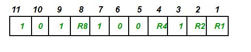
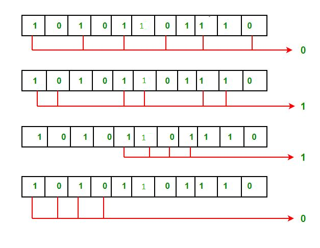
Determining the Parity bits –
- R1 bit is calculated using parity check at all the bits positions whose binary representation includes a 1 in the least significant position.R1: bits 1, 3, 5, 7, 9, 11
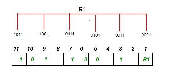 To find the redundant bit R1, we check for even parity. Since the total number of 1’s in all the bit positions corresponding to R1 is an even number the value of R1 (parity bit’s value) = 0
- R2 bit is calculated using parity check at all the bits positions whose binary representation includes a 1 in the second position from the least significant bit.R2: bits 2,3,6,7,10,11
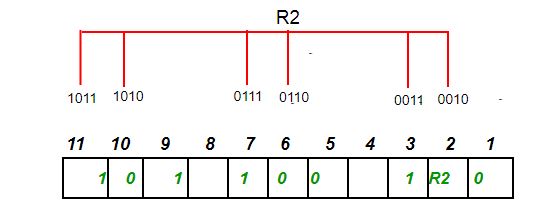 To find the redundant bit R2, we check for even parity. Since the total number of 1’s in all the bit positions corresponding to R2 is odd the value of R2(parity bit’s value)=1
 - R4 bit is calculated using parity check at all the bits positions whose binary representation includes a 1 in the third position from the least significant bit.R4: bits 4, 5, 6, 7
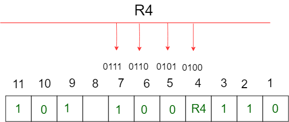 To find the redundant bit R4, we check for even parity. Since the total number of 1’s in all the bit positions corresponding to R4 is odd the value of R4(parity bit’s value) = 1
 - R8 bit is calculated using parity check at all the bits positions whose binary representation includes a 1 in the fourth position from the least significant bit.R8: bit 8,9,10,11
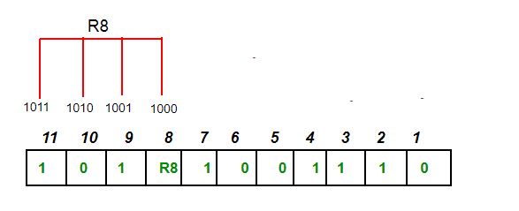 To find the redundant bit R8, we check for even parity. Since the total number of 1’s in all the bit positions corresponding to R8 is an even number the value of R8(parity bit’s value)=0.Thus, the data transferred is:
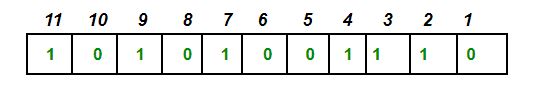
Error detection and correction –
Suppose in the above example the 6th bit is changed from 0 to 1 during data transmission, then it gives new parity values in the binary number:
Suppose in the above example the 6th bit is changed from 0 to 1 during data transmission, then it gives new parity values in the binary number:
 ‘
‘
The bits give the binary number as 0110 whose decimal representation is 6. Thus, the bit 6 contains an error. To correct the error the 6th bit is changed from 1 to 0.