Showing posts with label Hamming Code. Show all posts

Wednesday, December 20, 2023

Hamming Code in Computer Network

 Hamming code is a set of error-correction codes that can be used to detect and correct the errors that can occur when the data is moved or stored from the sender to the receiver. It is a technique developed by R.W. Hamming for error correction. Redundant bits – Redundant bits are extra binary bits that are generated and added to the information-carrying bits of data transfer to ensure that no bits were lost during the data transfer. The number of redundant bits can be calculated using the following formula:

 2^r ≥ m + r + 1 
 where, r = redundant bit, m = data bit

Suppose the number of data bits is 7, then the number of redundant bits can be calculated using: = 2^4 ≥ 7 + 4 + 1 Thus, the number of redundant bits= 4 Parity bits.  A parity bit is a bit appended to a data of binary bits to ensure that the total number of 1’s in the data is even or odd. Parity bits are used for error detection. There are two types of parity bits:

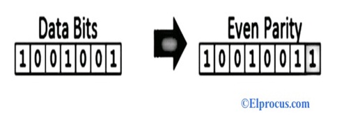
  1. Even parity bit: In the case of even parity, for a given set of bits, the number of 1’s are counted. If that count is odd, the parity bit value is set to 1, making the total count of occurrences of 1’s an even number. If the total number of 1’s in a given set of bits is already even, the parity bit’s value is 0.
  2. Odd Parity bit – In the case of odd parity, for a given set of bits, the number of 1’s are counted. If that count is even, the parity bit value is set to 1, making the total count of occurrences of 1’s an odd number. If the total number of 1’s in a given set of bits is already odd, the parity bit’s value is 0.

General Algorithm of Hamming code: Hamming Code is simply the use of extra parity bits to allow the identification of an error.

  1. Write the bit positions starting from 1 in binary form (1, 10, 11, 100, etc).
  2. All the bit positions that are a power of 2 are marked as parity bits (1, 2, 4, 8, etc).
  3. All the other bit positions are marked as data bits.
  4. Each data bit is included in a unique set of parity bits, as determined its bit position in binary form. a. Parity bit 1 covers all the bits positions whose binary representation includes a 1 in the least significant position (1, 3, 5, 7, 9, 11, etc). b. Parity bit 2 covers all the bits positions whose binary representation includes a 1 in the second position from the least significant bit (2, 3, 6, 7, 10, 11, etc). c. Parity bit 4 covers all the bits positions whose binary representation includes a 1 in the third position from the least significant bit (4–7, 12–15, 20–23, etc). d. Parity bit 8 covers all the bits positions whose binary representation includes a 1 in the fourth position from the least significant bit bits (8–15, 24–31, 40–47, etc). e. In general, each parity bit covers all bits where the bitwise AND of the parity position and the bit position is non-zero.
  5. Since we check for even parity set a parity bit to 1 if the total number of ones in the positions it checks is odd.
  6. Set a parity bit to 0 if the total number of ones in the positions it checks is even.


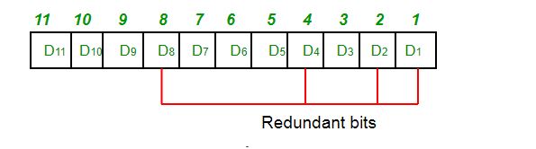
Determining the position of redundant bits – These redundancy bits are placed at positions that correspond to the power of 2. 

As in the above example:

  • The number of data bits = 7
  • The number of redundant bits = 4
  • The total number of bits = 11
  • The redundant bits are placed at positions corresponding to power of 2- 1, 2, 4, and 8

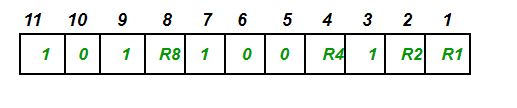
  • Suppose the data to be transmitted is 1011001, the bits will be placed as follows: 

Determining the Parity bits:

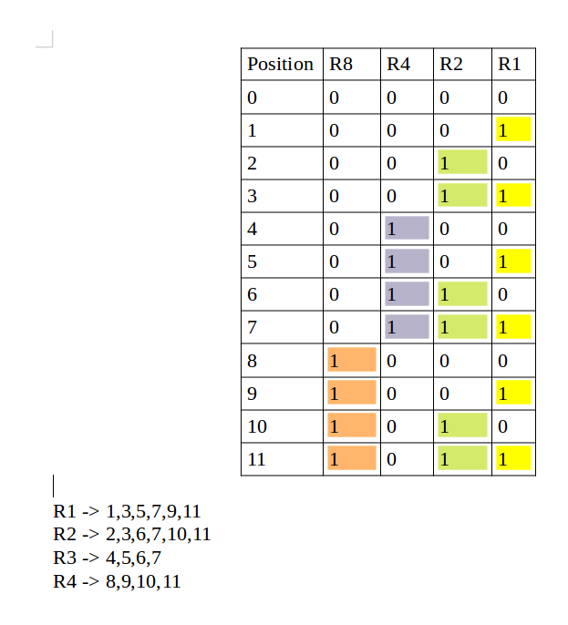
  • R1 bit is calculated using parity check at all the bits positions whose binary representation includes a 1 in the least significant position. R1: bits 1, 3, 5, 7, 9, 11 

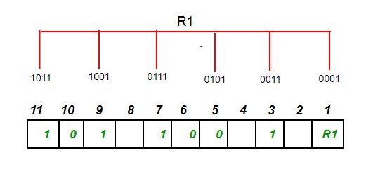
  • To find the redundant bit R1, we check for even parity. Since the total number of 1’s in all the bit positions corresponding to R1 is an even number the value of R1 (parity bit’s value) = 0
  • R2 bit is calculated using parity check at all the bits positions whose binary representation includes a 1 in the second position from the least significant bit. R2: bits 2,3,6,7,10,11 

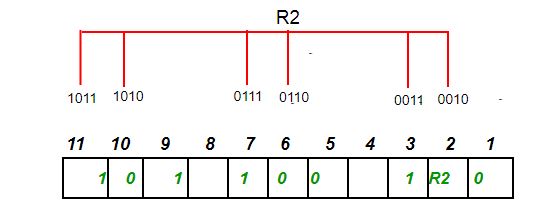
  • To find the redundant bit R2, we check for even parity. Since the total number of 1’s in all the bit positions corresponding to R2 is odd the value of R2(parity bit’s value)=1
  • R4 bit is calculated using parity check at all the bits positions whose binary representation includes a 1 in the third position from the least significant bit. R4: bits 4, 5, 6, 7 


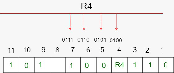
  1.  To find the redundant bit R4, we check for even parity. Since the total number of 1’s in all the bit positions corresponding to R4 is odd the value of R4(parity bit’s value) = 1
  2. R8 bit is calculated using parity check at all the bits positions whose binary representation includes a 1 in the fourth position from the least significant bit. R8: bit 8,9,10,11 
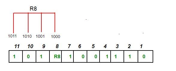
  • To find the redundant bit R8, we check for even parity. Since the total number of 1’s in all the bit positions corresponding to R8 is an even number the value of R8(parity bit’s value)=0. Thus, the data transferred is:

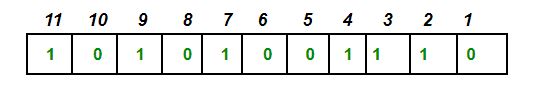
Error detection and correction: Suppose in the above example the 6th bit is changed from 0 to 1 during data transmission, then it gives new parity values in the binary number: 

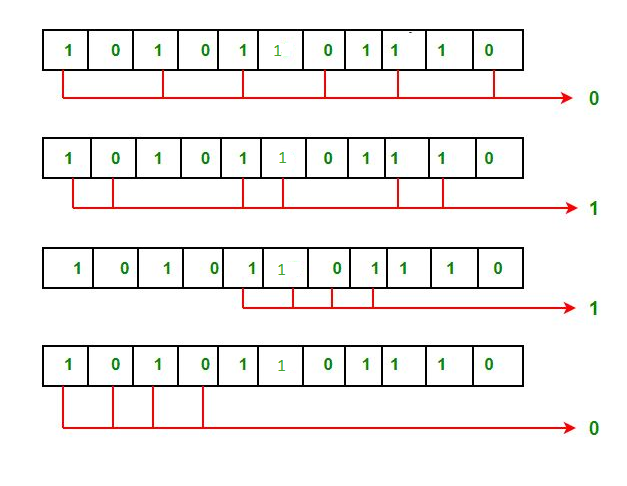
For all the parity bits we will check the number of 1’s in their respective bit positions.

For R1: bits 1, 3, 5, 7, 9, 11. We can see that the number of 1’s in these bit positions are 4 and that’s even so we get a 0 for this.

For R2: bits 2,3,6,7,10,11 . We can see that the number of 1’s in these bit positions are 5 and that’s odd so we get a 1 for this.

For R4: bits 4, 5, 6, 7 . We can see that the number of 1’s in these bit positions are 3 and that’s odd so we get a 1 for this.

For R8: bit 8,9,10,11 . We can see that the number of 1’s in these bit positions are 2 and that’s even so we get a 0 for this.

The bits give the binary number 0110 whose decimal representation is 6. Thus, bit 6 contains an error. To correct the error the 6th bit is changed from 1 to 0.

 Here are some of the features of Hamming code:

Error Detection and Correction: Hamming code is designed to detect and correct single-bit errors that may occur during the transmission of data. This ensures that the recipient receives the same data that was transmitted by the sender.

Redundancy: Hamming code uses redundant bits to add additional information to the data being transmitted. This redundancy allows the recipient to detect and correct errors that may have occurred during transmission.

Efficiency: Hamming code is a relatively simple and efficient error-correction technique that does not require a lot of computational resources. This makes it ideal for use in low-power and low-bandwidth communication networks.

Widely Used: Hamming code is a widely used error-correction technique and is used in a variety of applications, including telecommunications, computer networks, and data storage systems.

Single Error Correction: Hamming code is capable of correcting a single-bit error, which makes it ideal for use in applications where errors are likely to occur due to external factors such as electromagnetic interference.

Limited Multiple Error Correction: Hamming code can only correct a limited number of multiple errors. In applications where multiple errors are likely to occur, more advanced error-correction techniques may be required.

What is Hamming Code : History, Working and Its Applications

 In digital systems, the transmitted data for communication can be corrupted due to external noise and any other physical failures. If the transmitted data is not matched with the given input data, then it is called an ‘error’. The data errors can delete vital data in digital systems. The transfer of data will be in the form of bits ( 0 and 1) in digital systems. If anyone of the bit is changed, then the entire system’s performance can be affected. If the bit ‘1’ is changed to the bit ‘0’ or vice versa, then it is called bit error. There are different types of errors like single bit errors, multiple errors and burst errors. In this article, we discuss error correction and detection, and hamming code.


What is Error Detection and Correction?

In digital communication, the data will be lost if there is an error in the transfer of information from one system/network to another system/network. So, it is important to find and correct errors. Some error detection and correction methods are used to detect and correct the errors for effective communication. If these methods are used, then the data can be transferred with higher accuracy.

Error detection is defined as, the method used to detect the errors transmitted from transmitter/sender to receiver in digital systems. Redundancy codes are added to the data during the transmission to find the errors. These are called error-detecting codes.

Error correction is the correction of data transmitted from transmitter to receiver. Error correction can be done in two types.

Backward Error Correction

In this type of error correction, the receiver requests back the sender to retransmit the data if the receiver detects the error.

Forward Error Correction

if the data received by the receiver finds the error, then it executes the error-correcting codes, to correct and recover the data automatically.

If there is ‘m’ no.of data bits and ‘r’ no.of redundant bits, then the combinations of information will be 2r.

2r > = m+r+1

Types of Error Detection Codes

The errors in the received data can be detected by using 3 types of error detection codes. They are, parity check, cyclic redundancy check (CRC) and longitudinal redundancy check.

Parity Check

The redundant bit called parity bit is added to make the no.of bits even or odd in case of even parity or odd parity. The receiver counts the no.of bits ( 1’s) in a frame to add the parity bit. This is called parity checking. If the no.of 1’s in a frame is even, then even parity is used by adding the bit ‘1’with zero value. Similarly, of the no.of 1’s is odd, then the odd parity is used by adding the bit with value ‘1’.

Error-Detection
error-detection

Hence, it is used to ensure that the frame/date received by the receiver from the source is not corrupted. In this type of error detection, the no.of 1’s should be even in the received frame. It is very less expensive among all types of error detection.

Longitudinal Redundancy Check(LRC)

hen the set/block of bits are organized, then the LRC method can be used to check the parity bit in every frame. It helps to send the set of parity bits along with the original data and checks the redundancy.

Cyclic Redundancy Check

his type is used to detect the data/frame received from the source is valid or not. It involves in the binary division of the data that should be sent and uses polynomials (to generate divisor). Before the transmission, a division operation is performed by the sender on the data/bits/frame to calculate the remainder.

Cyclic-Redundancy-Check
cyclic-redundancy-check

During the transmission of actual data from the sender, it adds the remainder at the end of the actual data. The combination of actual data and the remainder is called a codeword. The data is transmitted in the form of codewords. In this process, if the data is corrupted, then the data will be rejected by the receiver otherwise it will be accepted.

What is the Hamming Code?

Hamming code is defined as, a linear code that is used in the error detection process up to 2-intermediate errors. It is also capable of detecting single-bit errors. In this method, the redundant bits are added to the data/message by the sender to encode the data. In order to do error detection and correction, these redundant bits are added in certain positions for the error correction process.

Hamming-Code
hamming-code

History of Hamming Codes

In 1950, Richard W. hamming invented Hamming codes to detect and correct the errors in data. After the evolution of computers with higher reliability, he introduced hamming codes for 1-error correcting codes and later on he extended up to 2-error detecting codes. Hamming codes are created because parity check cannot detect and correct errors in the data. The Hamming codes are inserted to any blocklength of data between actual data and redundancy bits. He developed an array of algorithms to work on the problems of error correction methods and these codes are widely used in ECC memory.

Process of Encoding a Message using Hamming Code

The process of encoding a message using a hamming code by the sender includes 3 steps.

Step1: The first step is to calculate the no.of redundant bits in a message

  • For example, if a message contains ‘n’ no.of bits and ‘p’ no.of redundant bits are added to the message, then ‘np’ indicates (n+p+1) different states.
  • Where (n+p) represents the location of an error in every bit position
  • 1 (extra state) represents no error.
  • Since ‘p’ indicates 2^p (2p ) states, which are equal to (n+p+1) states.

Step2: Place the redundant bits in exact/correct position

‘p’ bits are inserted in the bit positions which are the power of 2 like 1, 2, 4, 8, 16, etc. These bit positions are indicated as p1 (position 1), p2 (position 2), p3 (position 4), etc.

Step 3: Calculate the values of redundant bits

  • Here parity bits are used to calculate the values of redundant bits.
  • Parity bits can make the no.of 1’s in a message either even or odd.
  • If total no.of 1’s in a message is even, then even parity is used
  • If total no.of 1’s in a message is odd, then odd parity is used.

Process of Decrypting a Message in Hamming Code

The process of decrypting a message received from the sender by the receiver using the hamming code includes the following steps. This process is nothing but recalculation to detect and correct the errors in a message.

Step1: Count the no.of redundant bits

The formula to encode the message using redundant bits is,

2p≥ n + p + 1

Step 2: correct the positions of all redundant bits

‘p’ no.of redundant bits are placed in a bit positions of power of 2 like 1,2,4,8,16,32 etc

Step3: parity checking (odd parity and even parity)

Parity bits are calculated based on the no.of 1’s in data bits and redundant bits.

For Example

Parity of p1 would be 1, 3, 5, 7, 9, 11,…

Parity of p2 would be 2, 3, 6, 7, 10, 11,…

Parity of p3 would be 4-7, 12-15, 20-23,…

Advantages of Hamming Code

The main advantage of using a hamming code is cost-effective if a data stream contains single-bit errors.

  • It can provide error detection and also indicates the bit which contains an error for correction.
  • Hamming codes are very easy and best to use in computer memory and single-bit error correction and detection.

Disadvantages of Hamming Code

  • It is best only for single-bit error correction and detection. If multiple bits errors, then the entire can be corrupted.
  • The Hamming code algorithm can resolve only single-bit errors.

Applications of Hamming Codes

Hamming codes are used in,

  • Computing
  • Telecommunications
  • Data compression
  • Solving puzzles and turbo codes
  • Satellites
  • Plasma CAM
  • Shielded wires
  • Modems
  • Computer memory
  • Open connectors
  • Embedded systems and processor

FAQs

1). Can the Hamming code detect 2-bit errors?

Hamming codes can detect and correct up to 2-bit errors in a data stream

2). How do you fix the Hamming code?

Hamming codes are placed in any length of data between the actual data and redundant bits. These codes are places with a minimum distance of 3 bits

3). What is the parity code?

Parity code or parity bit is adding a bit to the received frame ( data contains 1’s and 0’s) to make total no.of bits (1’s) even or odd.

4). What is the Hamming distance between the data?

The hamming distance between the two different data streams of equal length is no.of 1’s.

The hamming distance between two data strings of equal length can be calculated by using the XOR operation.

For example, a=11011001

b=10011101

Hamming distance can be calculated as,

11011001 ⊕ 10011101 = 01000100 (no.of 1-bits are 2)

The hamming distance indicates the no.of 1’s in the resultant data stream

So, d(11011001, 10011101) = 2

Similarly, 010 ⊕ 011 = 001, d(010, 011) = 1.

5). Is Hamming code cyclic?

Yes, hamming codes are equivalent to cyclic codes that can be used as error-detecting codes.

..

Hamming Code

 There are two ways to handle the error correction:

  1. Whenever an error discovered, the receiver can have the sender in order to retransmit the entire data unit. This technique is known as the Backward Error correction technique. This technique is simple and inexpensive in the case of wired transmission like fiber optics; there is no expense in retransmitting the data. In the case of wireless transmission, retransmission costs too much thus forward error correction technique is used then.

  2. The receiver can use an error-correcting code that automatically contains certain errors. This technique is known as the Forward Error Correction technique.

In order to correct the errors, one has to know the exact position of the error. For example, In case if we want to calculate a single-bit error, the error correction code then mainly determines which one of seven bits is in the error.

In order to achieve this, we have to add some additional redundant bits.

Suppose r (as the redundant bits) and d indicates the total number of data bits. In order to calculate the redundant bits(r), the given formula is used;

2r= d+r+1

Error correction is mainly done with the help of the Hamming code.

Hamming Code

It is a technique developed by R.W. hamming. This can be applied to data units of any length. This code mainly uses the relationship between data and redundancy bits.

The hamming code technique, which is an error-detection and error-correction technique, was proposed by R.W. Hamming. Whenever a data packet is transmitted over a network, there are possibilities that the data bits may get lost or damaged during transmission.

Let's understand the Hamming code concept with an example:

Let's say you have received a 7-bit Hamming code which is 1011011.

First, let us talk about the redundant bits.

The redundant bits are some extra binary bits that are not part of the original data, but they are generated & added to the original data bit. All this is done to ensure that the data bits don't get damaged and if they do, we can recover them.

Now the question arises, how do we determine the number of redundant bits to be added?

We use the formula, 2r >= m+r+1; where r = redundant bit & m = data bit.

From the formula we can make out that there are 4 data bits and 3 redundancy bits, referring to the received 7-bit hamming code.

What is Parity Bit?

To proceed further we need to know about parity bit, which is a bit appended to the data bits which ensures that the total number of 1's are even (even parity) or odd (odd parity).

While checking the parity, if the total number of 1's are odd then write the value of parity bit P1(or P2 etc.) as 1 (which means the error is there ) and if it is even then the value of parity bit is 0 (which means no error).

Hamming Code in Error Detection

As we go through the example, the first step is to identify the bit position of the data & all the bit positions which are powers of 2 are marked as parity bits (e.g. 1, 2, 4, 8, etc.). The following image will help in visualizing the received hamming code of 7 bits.

hamming code - error detection

First, we need to detect whether there are any errors in this received hamming code.

Step 1: For checking parity bit P1, use check one and skip one method, which means, starting from P1 and then skip P2, take D3 then skip P4 then take D5, and then skip D6 and take D7, this way we will have the following bits,

hamming code - error detection

As we can observe the total number of bits is odd so we will write the value of parity bit as P1 = 1. This means the error is there.

Step 2: Check for P2 but while checking for P2, we will use the check two and skip two methods, which will give us the following data bits. But remember since we are checking for P2, so we have to start our count from P2 (P1 should not be considered).

hamming code - error correction and detection

As we can observe that the number of 1's are even, then we will write the value of P2 = 0. This means there is no error.

Step 3: Check for P4 but while checking for P4, we will use the check four and skip four methods, which will give us the following data bits. But remember since we are checking for P4, so we have started our count from P4(P1 & P2 should not be considered).

hamming code - error correction and detection

As we can observe that the number of 1's is odd, then we will write the value of P4 = 1. This means the error is there.

So, from the above parity analysis, P1 & P4 are not equal to 0, so we can clearly say that the received hamming code has errors.

Hamming Code: Error Correction

Since we found that the received code has an error, so now we must correct them. To correct the errors, use the following steps:

Now the error word E will be:

Hamming Code: Error Correction

Now we have to determine the decimal value of this error word 101 which is 5.

We get E = 5, which states that the error is in the fifth data bit. To correct it, just invert the fifth data bit.

So the correct data will be:

Hamming Code: Error Correction

Reference1

Reference