Transmission media is a communication channel that carries the information from the sender to the receiver. Data is transmitted through the electromagnetic signals.
The main functionality of the transmission media is to carry the information in the form of bits through LAN(Local Area Network).
It is a physical path between transmitter and receiver in data communication.
In a copper-based network, the bits in the form of electrical signals.
In a fibre based network, the bits in the form of light pulses.
In OSI(Open System Interconnection) phase, transmission media supports the Layer 1. Therefore, it is considered to be as a Layer 1 component.
The electrical signals can be sent through the copper wire, fibre optics, atmosphere, water, and vacuum.
The characteristics and quality of data transmission are determined by the characteristics of medium and signal.
Transmission media is of two types are wired media and wireless media. In wired media, medium characteristics are more important whereas, in wireless media, signal characteristics are more important.
Different transmission media have different properties such as bandwidth, delay, cost and ease of installation and maintenance.
The transmission media is available in the lowest layer of the OSI reference model, i.e., Physical layer.
Some factors need to be considered for designing the transmission media:
Bandwidth: All the factors are remaining constant, the greater the bandwidth of a medium, the higher the data transmission rate of a signal.
Transmission impairment: When the received signal is not identical to the transmitted one due to the transmission impairment. The quality of the signals will get destroyed due to transmission impairment.
Interference: An interference is defined as the process of disrupting a signal when it travels over a communication medium on the addition of some unwanted signal.
Causes Of Transmission Impairment:
Attenuation: Attenuation means the loss of energy, i.e., the strength of the signal decreases with increasing the distance which causes the loss of energy.
Distortion: Distortion occurs when there is a change in the shape of the signal. This type of distortion is examined from different signals having different frequencies. Each frequency component has its own propagation speed, so they reach at a different time which leads to the delay distortion.
Noise: When data is travelled over a transmission medium, some unwanted signal is added to it which creates the noise.
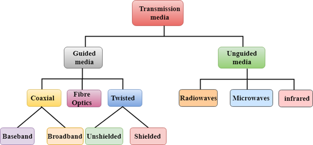
The physical means by which data is transmitted from one geographic or electronic location to another is called transmission, or "communication" media. There are two categories of transmission media used in network communications.
Bounded or guided media
Unbounded or unguided media
Bounded Media
Bounded media are physical cables that signals travel through on a narrow path. Also known as guided media, bounded media are made up of an external conductor (usually copper) wrapped in a jacket made of nonconductive material. Bounded media are great for in-lab communications because they offer high speeds, are more secure than unbounded media and are low-cost. A downfall of bounded media are distance constraints; one can only use bounded media as far as they can afford cable, and attenuation can prevent connections over longer distances. Three common types of bounded media are used in data transmission. These are:
Coaxial Cable
Twisted-Pair Cable
Fiber Optic Cable
1. Coaxial Cable
Coaxial cable is a widely used type of transmission media. For example, a TV wire is usually coaxial.
Coaxial cable is named after the two conductors that run parallel to each other. The center conductor in the cable is usually copper, which is usually either a solid wire or stranded, twisted copper.
Outside this central conductor is a non-conductive material called a dielectric insulator. It is usually a white, plastic material used to separate the inner conductor from the outer conductor. The other conductor is a fine mesh made from braided copper. It is used to help shield the cable from electromagnetic interference, or EMI.
Wrapped outside the copper mesh is the final non-conductive protective cover.
The actual data travels through the center conductor in the cable. EMI is "caught", or redirected, by the outer copper mesh. There are different types of coaxial cable that vary by gauge and impedance.
"Gauge" is the thickness of a given cable. It is measured by the radio guide measurement or RG number. The higher the RG number, the thinner the central core conductor. The lower the RG number, the thicker the core conductor.
The following are the most common coaxial standards:
50-Ohm RG-7 or RG-11: Used for thick Ethernet or "thicknet".
50-Ohm RG-58: Used for thin Ethernet, or "cheapernet".
75-Ohm RG-59: Used for cable television.
93-Ohm RG-62: Used for ARCNET.
Coaxial cable
Characteristics of Coaxial Cabling
Advantages of Coaxial Cable
low cost
easy to install
easy to expand
up to 10 Mbps (megabits of data per second) capacity
medium resistant to EMI
Disadvantages of Coaxial Cable
Single cable failure, also known as a single point of failure, can take down an entire network.
Coaxial cable is an attenuating medium that results in a gradual weakening of transmission the further data gets from the point of origin.
STP
UTP
2. Twisted-Pair Cabling
The most popular network cabling is twisted-pair cabling. It is light-weight, easy to install, inexpensive, and supports a variety of networks. In addition, it supports a data speed of up to 100 Mbps. Twisted-pair cabling is made of pairs of solid or stranded copper twisted along each other. The twists are to reduce vulnerability to EMI and crosstalk. The number of pairs in the cable depends on the type of cable.
The copper core is usually 22-AWG or 24-AWG, as measured by the American Wire Gauge standard. AWG is the U.S. measurement standard for the gauge of the conductive core in wiring. There are two types of twisted-pair cables:
1. Unshielded twisted-pair (UTP)
2. Shielded twisted-pair (STP)
2.1 Unshielded Twisted-Pair (UTP)
UTP wiring is more common than STP. UTP can be either voice-grade or data-grade. UTP cable normally has an impedance of 100 Ohms. UTP cost less than STP and is easily available due to its many uses. There are five levels of data cabling for UTP cabling:
Category 1: These are used in telephone lines and low-speed data systems.
Category 2: These cables can support up to 4 MPS implementation.
Category 3: These cables support up to 16 MPS and are mostly used in 10 MPS environments.
Category 4: These are used for larger distances and high speeds. It can support 20 MPS.
Category 5: This is the highest rating for UTP cable and can support up to 100 MPS.
UTP cables consist of two or four pairs of twisted cable. Cable with two pairs uses RJ-11 connectors and four-pair cables use an RJ-45 connector.
Characteristics of UTP
low cost
easy to install
high-speed capacity
high attenuation
effective to EMI
100-meter limit
Advantages of UTP
easy installation
capable of high speed for LAN
low cost
Disadvantages of UTP
short-range capability due to attenuation
2.2Shielded Twisted-Pair (STP)
STP is similar to UTP but has a mesh shielding that protects transmissions from EMI. This allows for a faster transmission rate.
IBM has defined categories for STP cable:
Type 1: STP features two pairs of 22-AWG.
Type 2: This type includes type 1 with 4 telephone pairs.
Type 6: This type features two pairs of standard shielded 26-AWG.
Type 7: This type of STP consists of 1 pair of standard shielded 26-AWG.
Type 9: This type consists of shielded 26-AWG wire.
Characteristics of STP:
medium cost
easy to install
higher capacity than UTP
higher attenuation, but same as UTP
medium immunity from EMI
100-meter limit
Advantages of STP:
shielded
faster than UTP and coaxial
Disadvantages of STP:
more expensive than UTP and coaxial
more difficult installation
high attenuation rate
Fiber Optics
Fiber optic cable uses light signals to transmit data. In fiber optics, light only moves in one direction, so for two-way communication to take place a second connection must be made between the two devices. To accomplish this, fiber optics are manufactured with two strands of cable running in parallel. Each strand is responsible for one direction of communication. A laser on one device sends pulses of light through this cable to the other device. These pulses translated into “1’s” and “0’s” at the other end. A response is sent from the receiving computer through the parallel cable.
In the center of fiber cable is a glass strand or core. The light from the laser moves through this glass to the other device. Around the internal core is a reflective material known as cladding. No light escapes the glass core because of this reflective cladding.
Fiber optic cable has a bandwidth of more than 2 Gbps (gigabytes per second).