When data is transmitted from one device to another device, the system does not guarantee whether the data received by the device is identical to the data transmitted by another device. An Error is a situation when the message received at the receiver end is not identical to the message transmitted.
Types Of Errors
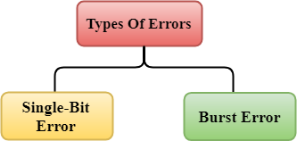
Errors can be classified into two categories:
- Single-Bit Error
- Burst Error
Single-Bit Error:
The only one bit of a given data unit is changed from 1 to 0 or from 0 to 1.

In the above figure, the message which is sent is corrupted as single-bit, i.e., 0 bit is changed to 1.
Single-Bit Error does not appear more likely in Serial Data Transmission. For example, Sender sends the data at 10 Mbps, this means that the bit lasts only for 1 ?s and for a single-bit error to occurred, a noise must be more than 1 ?s.
Single-Bit Error mainly occurs in Parallel Data Transmission. For example, if eight wires are used to send the eight bits of a byte, if one of the wire is noisy, then single-bit is corrupted per byte.
Burst Error:
The two or more bits are changed from 0 to 1 or from 1 to 0 is known as Burst Error.
The Burst Error is determined from the first corrupted bit to the last corrupted bit.
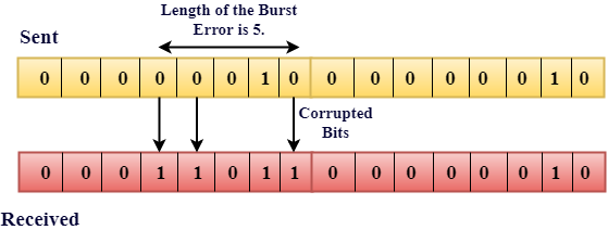
The duration of noise in Burst Error is more than the duration of noise in Single-Bit.
Burst Errors are most likely to occurr in Serial Data Transmission.
The number of affected bits depends on the duration of the noise and data rate.
Error Detecting Techniques:
The most popular Error Detecting Techniques are:
- Single parity check
- Two-dimensional parity check
- Checksum
- Cyclic redundancy check
Single Parity Check
- Single Parity checking is the simple mechanism and inexpensive to detect the errors.
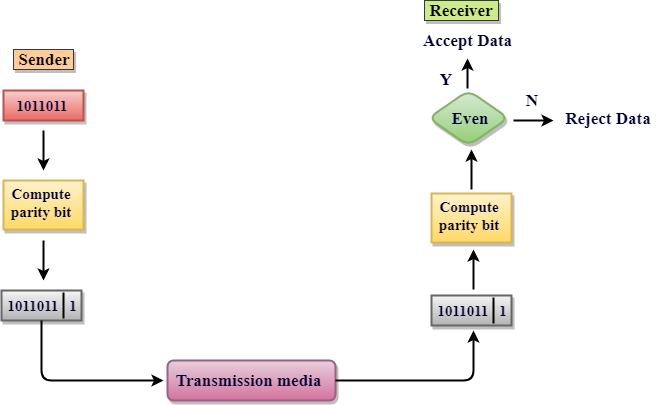
- In this technique, a redundant bit is also known as a parity bit which is appended at the end of the data unit so that the number of 1s becomes even. Therefore, the total number of transmitted bits would be 9 bits.
- If the number of 1s bits is odd, then parity bit 1 is appended and if the number of 1s bits is even, then parity bit 0 is appended at the end of the data unit.
- At the receiving end, the parity bit is calculated from the received data bits and compared with the received parity bit.
- This technique generates the total number of 1s even, so it is known as even-parity checking.
Drawbacks Of Single Parity Checking
- It can only detect single-bit errors which are very rare.
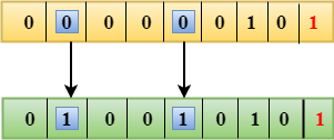
- If two bits are interchanged, then it cannot detect the errors.
Two-Dimensional Parity Check
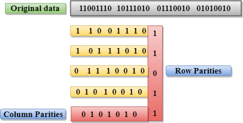
- Performance can be improved by using Two-Dimensional Parity Check which organizes the data in the form of a table.
- Parity check bits are computed for each row, which is equivalent to the single-parity check.
- In Two-Dimensional Parity check, a block of bits is divided into rows, and the redundant row of bits is added to the whole block.
- At the receiving end, the parity bits are compared with the parity bits computed from the received data.
Drawbacks Of 2D Parity Check
- If two bits in one data unit are corrupted and two bits exactly the same position in another data unit are also corrupted, then 2D Parity checker will not be able to detect the error.
- This technique cannot be used to detect the 4-bit errors or more in some cases.
Checksum
A Checksum is an error detection technique based on the concept of redundancy.
It is divided into two parts:
Checksum Generator
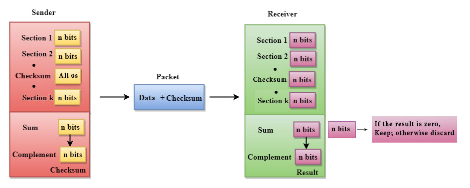
A Checksum is generated at the sending side. Checksum generator subdivides the data into equal segments of n bits each, and all these segments are added together by using one's complement arithmetic. The sum is complemented and appended to the original data, known as checksum field. The extended data is transmitted across the network.
Suppose L is the total sum of the data segments, then the checksum would be ?L
Checksum Checker
A Checksum is verified at the receiving side. The receiver subdivides the incoming data into equal segments of n bits each, and all these segments are added together, and then this sum is complemented. If the complement of the sum is zero, then the data is accepted otherwise data is rejected.
Cyclic Redundancy Check (CRC)
CRC is a redundancy error technique used to determine the error.
Following are the steps used in CRC for error detection:
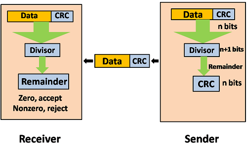
- In CRC technique, a string of n 0s is appended to the data unit, and this n number is less than the number of bits in a predetermined number, known as division which is n+1 bits.
- Secondly, the newly extended data is divided by a divisor using a process is known as binary division. The remainder generated from this division is known as CRC remainder.
- Thirdly, the CRC remainder replaces the appended 0s at the end of the original data. This newly generated unit is sent to the receiver.
- The receiver receives the data followed by the CRC remainder. The receiver will treat this whole unit as a single unit, and it is divided by the same divisor that was used to find the CRC remainder.
If the resultant of this division is zero which means that it has no error, and the data is accepted.
If the resultant of this division is not zero which means that the data consists of an error. Therefore, the data is discarded.
Let's understand this concept through an example:
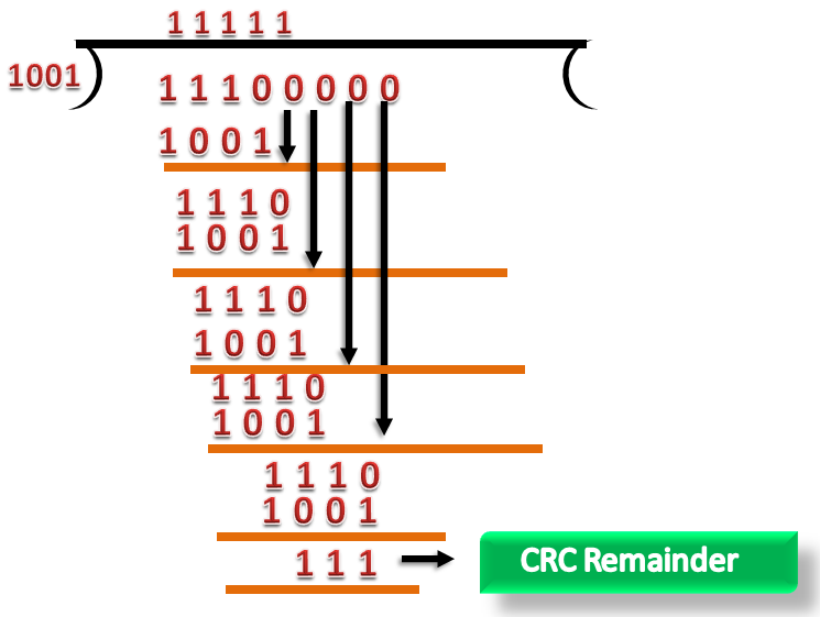
Suppose the original data is 11100 and divisor is 1001.
CRC Generator
- A CRC generator uses a modulo-2 division. Firstly, three zeroes are appended at the end of the data as the length of the divisor is 4 and we know that the length of the string 0s to be appended is always one less than the length of the divisor.
- Now, the string becomes 11100000, and the resultant string is divided by the divisor 1001.
- The remainder generated from the binary division is known as CRC remainder. The generated value of the CRC remainder is 111.
- CRC remainder replaces the appended string of 0s at the end of the data unit, and the final string would be 11100111 which is sent across the network.
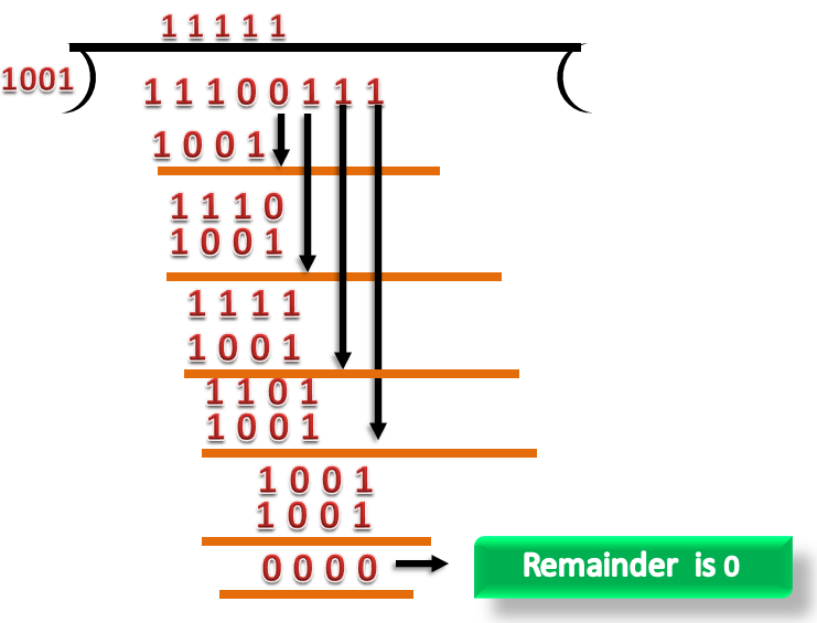
CRC Checker
- The functionality of the CRC checker is similar to the CRC generator.
- When the string 11100111 is received at the receiving end, then CRC checker performs the modulo-2 division.
- A string is divided by the same divisor, i.e., 1001.
- In this case, CRC checker generates the remainder of zero. Therefore, the data is accepted.
No comments:
Post a Comment